linear_elasticity/linear_elastic.py
Description
Linear elasticity with given displacements.
Find  such that:
where

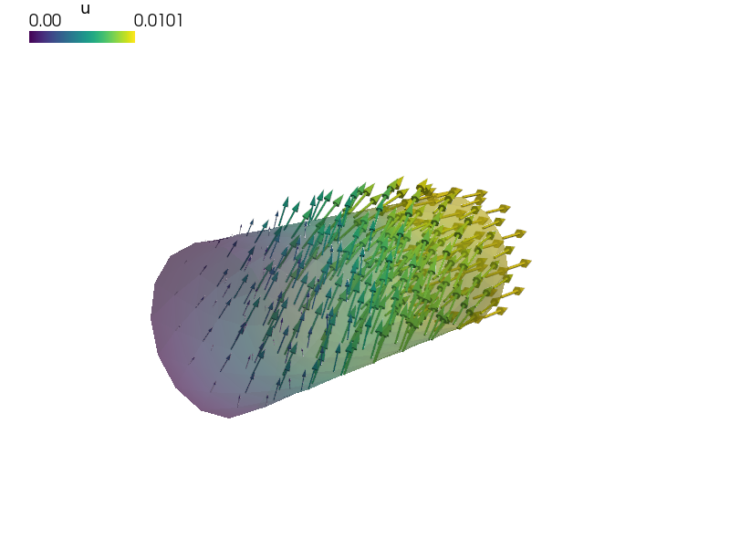
This example models a cylinder that is fixed at one end while the second end
has a specified displacement of 0.01 in the x direction (this boundary
condition is named 'Displaced'). There is also a specified displacement of
0.005 in the z direction for points in the region labeled
'SomewhereTop'. This boundary condition is named
'PerturbedSurface'. The region 'SomewhereTop' is specified as those
vertices for which:
(z > 0.017) & (x > 0.03) & (x < 0.07)
The displacement field (three DOFs/node) in the 'Omega region' is
approximated using P1 (four-node tetrahedral) finite elements. The material is
linear elastic and its properties are specified as Lamé parameters
 and
and  (see
http://en.wikipedia.org/wiki/Lam%C3%A9_parameters)
(see
http://en.wikipedia.org/wiki/Lam%C3%A9_parameters)
The output is the displacement for each vertex, saved by default to cylinder.vtk. View the results using:
sfepy-view cylinder.vtk -f u:wu 1:vw
# -*- coding: utf-8 -*-
r"""
Linear elasticity with given displacements.
Find :math:`\ul{u}` such that:
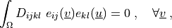
.. math::
\int_{\Omega} D_{ijkl}\ e_{ij}(\ul{v}) e_{kl}(\ul{u})
= 0
\;, \quad \forall \ul{v} \;,
where
.. math::
D_{ijkl} = \mu (\delta_{ik} \delta_{jl}+\delta_{il} \delta_{jk}) +
\lambda \ \delta_{ij} \delta_{kl}
\;.
This example models a cylinder that is fixed at one end while the second end
has a specified displacement of 0.01 in the x direction (this boundary
condition is named ``'Displaced'``). There is also a specified displacement of
0.005 in the z direction for points in the region labeled
``'SomewhereTop'``. This boundary condition is named
``'PerturbedSurface'``. The region ``'SomewhereTop'`` is specified as those
vertices for which::
(z > 0.017) & (x > 0.03) & (x < 0.07)
The displacement field (three DOFs/node) in the ``'Omega region'`` is
approximated using P1 (four-node tetrahedral) finite elements. The material is
linear elastic and its properties are specified as Lamé parameters
:math:`\lambda` and :math:`\mu` (see
http://en.wikipedia.org/wiki/Lam%C3%A9_parameters)
The output is the displacement for each vertex, saved by default to
cylinder.vtk. View the results using::
sfepy-view cylinder.vtk -f u:wu 1:vw
"""
from sfepy import data_dir
from sfepy.mechanics.matcoefs import stiffness_from_lame
filename_mesh = data_dir + '/meshes/3d/cylinder.mesh'
regions = {
'Omega' : 'all',
'Left' : ('vertices in (x < 0.001)', 'facet'),
'Right' : ('vertices in (x > 0.099)', 'facet'),
'SomewhereTop' : ('vertices in (z > 0.017) & (x > 0.03) & (x < 0.07)',
'vertex'),
}
materials = {
'solid' : ({'D': stiffness_from_lame(dim=3, lam=1e1, mu=1e0)},),
}
fields = {
'displacement': ('real', 'vector', 'Omega', 1),
}
integrals = {
'i' : 1,
}
variables = {
'u' : ('unknown field', 'displacement', 0),
'v' : ('test field', 'displacement', 'u'),
}
ebcs = {
'Fixed' : ('Left', {'u.all' : 0.0}),
'Displaced' : ('Right', {'u.0' : 0.01, 'u.[1,2]' : 0.0}),
'PerturbedSurface' : ('SomewhereTop', {'u.2' : 0.005}),
}
equations = {
'balance_of_forces' :
"""dw_lin_elastic.i.Omega(solid.D, v, u) = 0""",
}
solvers = {
'ls': ('ls.auto_direct', {}),
'newton': ('nls.newton', {
'i_max' : 1,
'eps_a' : 1e-10,
}),
}