Deformation of a foam-reinforced shell beam
FE Model
We consider a thin-walled beam made of steel fully fixed at its one end and loaded by a uniform load at the top edge of the second end. The beam is reinforced by a foam material placed inside it. The outer dimensions of the beam are 30x40 mm, the wall thickness is 2 mm, and its length is 400 mm. The thin-walled beam is modeled using shell10x elements and the foam part by the classical linear solid elements. The material properties of the constituents are summarized in the following table:
Young modulus |
Poisson ration |
|
|---|---|---|
steel |
210 GPa |
0.3 |
foam |
20 GPa |
0.25 |
The applied boundary conditions are depicted in Fig. 1.
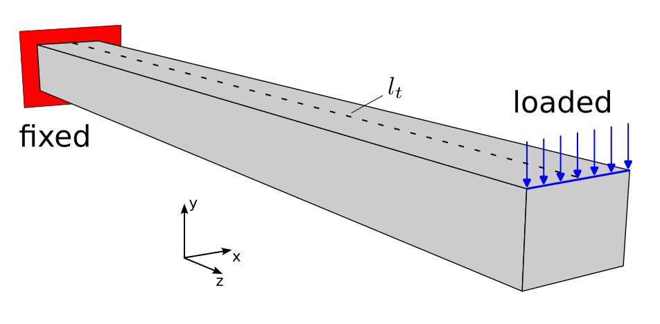
Fig. 1 Boundary conditions applied to the beam.
In order to show the credibility of the above model (see Fig. 2), we compare its results with the results of the following models:
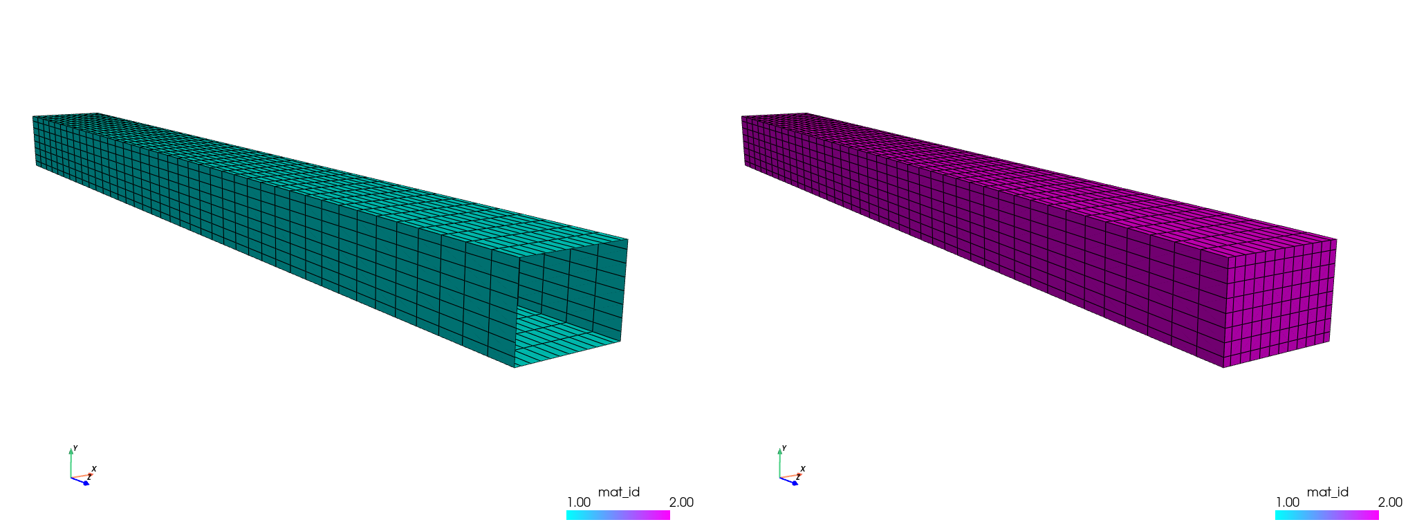
Fig. 2 Beam with foam reinforcement - shell10x + hexahedral elements.
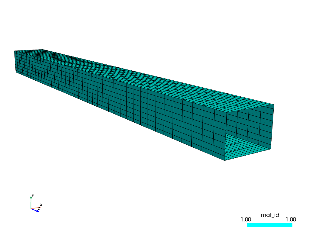
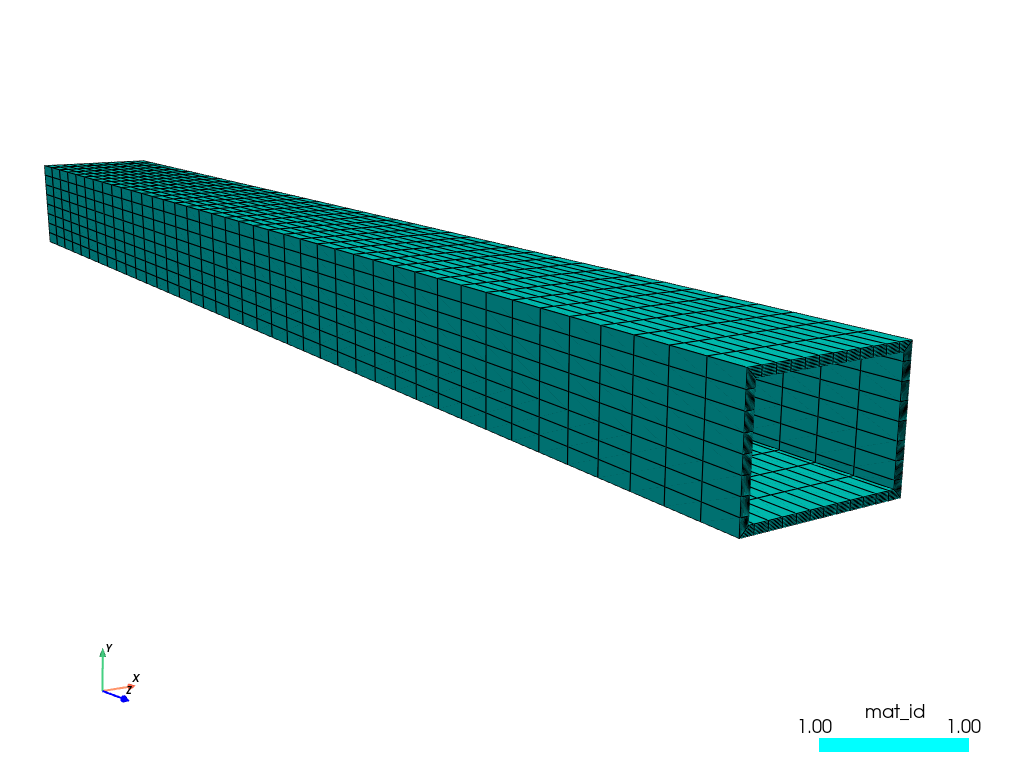
Fig. 4 Beam without reinforcement - solid hexahedral elements.
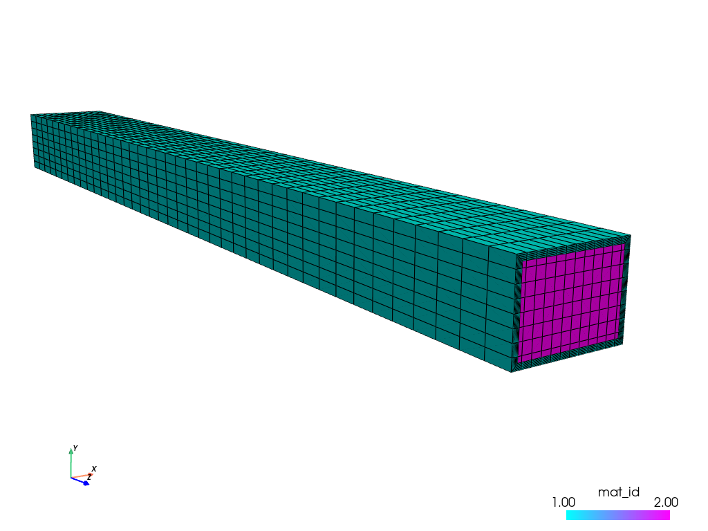
Fig. 5 Beam with foam reinforcement - solid hexahedral elements.
Running simulation
To run the numerical simulation, download the archive, unpack it and run by:
sfepy-run example_shell_beam-1/beam_shell.py
sfepy-run example_shell_beam-1/beam_solid.py
sfepy-run example_shell_beam-1/beam_shell_foam.py
sfepy-run example_shell_beam-1/beam_solid_foam.py
The finite element meshes can be generated using the gen_mesh.py script.
Results
To plot the deformed foam-reinforced structure run the following command:
sfepy-view results/beam_shell_foam.vtk -f uf:wuf:f10:m2:p0 0:vw:m2:p0 us_disp:wus_disp:f10:m1:p1 --camera-position="-0.4,0.16,0.57,0.02,0,0.23,0.22,0.97,-0.11" --grid-vector1="0, 1.6, 0"
The resulting image is depicted in Fig. 6.
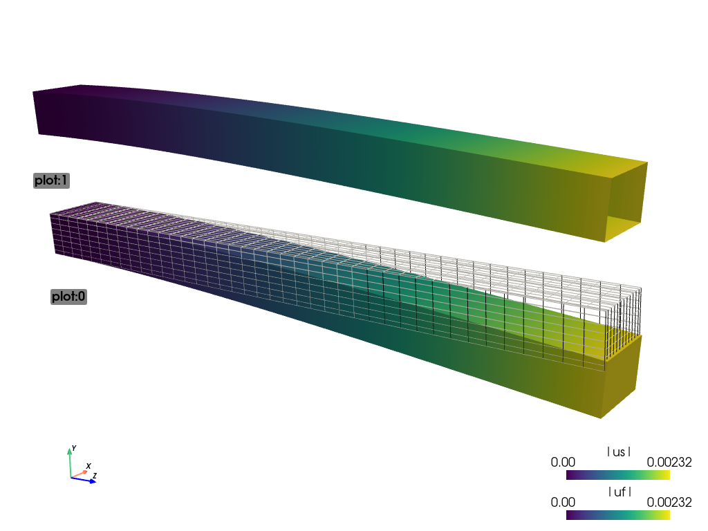
Fig. 6 Resulting displacements.
The displacements in the y-direction along line  (see
Fig. 1) obtained by the different models are compared in
Fig. 7. The figure is plotted by
(see
Fig. 1) obtained by the different models are compared in
Fig. 7. The figure is plotted by plot.py
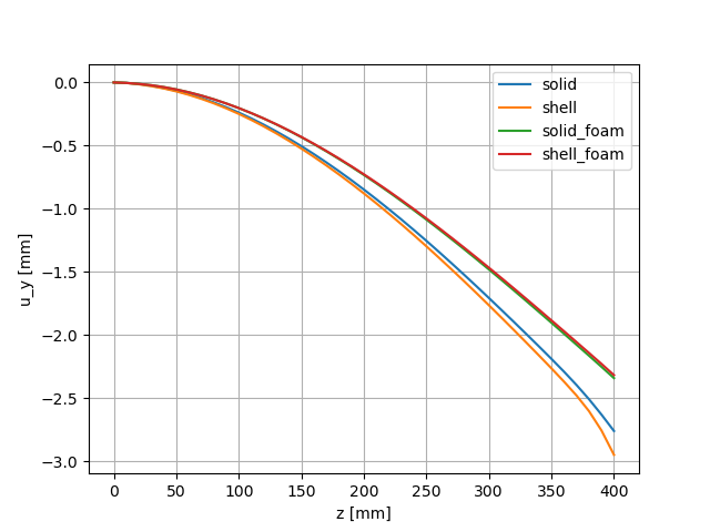
Fig. 7 Displacements along line .